")
")
")
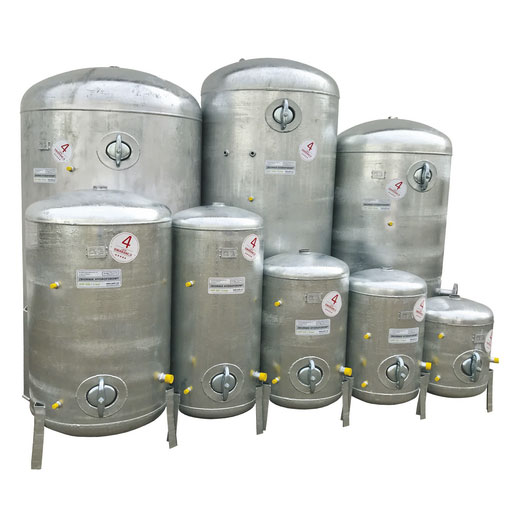
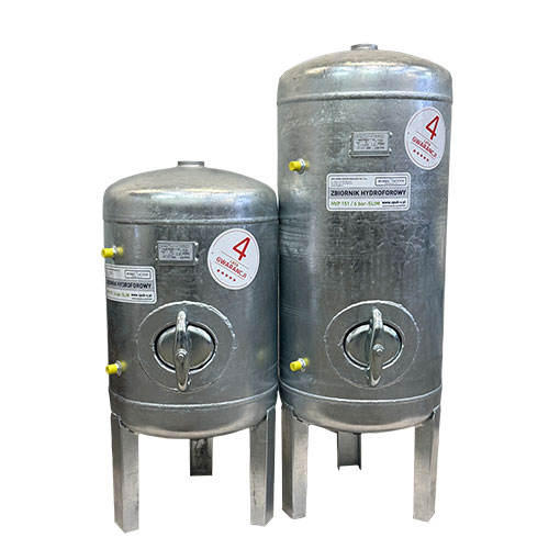
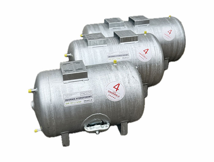
Hot-dip Galvanized Hydrophor Tanks – HVP Horizontal
HVP L horizontal tanks provide a solid and reliable foundation for building hydropneumatic systems with self-priming pumps. Thanks to their galvanized, corrosion-resistant construction, they offer long service life and trouble-free operation under various working conditions. HVP L horizontal tanks are ideal for domestic, agricultural, and industrial installations — wherever stable water pressure and an independent water supply are required.
Advantages of HVP L Horizontal Pressure Tanks
Durable, galvanized construction – corrosion-resistant protection ensures long service life and resistance to water and external factors.
Versatile applications – compatible with various types of self-priming pumps and hydropneumatic system automation.
Stable, horizontal design – allows safe pump installation directly on the tank, simplifying setup and saving space.
Customizable to your needs – available in multiple capacities.
Safe system operation – appropriate tank capacity and strength ensure smooth operation of the hydropneumatic system and stable water pressure.
HVP L horizontal tanks are widely used in:
- Domestic and agricultural water supply systems,
- Garden, greenhouse, and plantation irrigation systems,
- Industrial installations requiring consistent pressure,
- Small local water networks and public utility buildings,
- Hydropneumatic systems with self-priming pumps.
Tank Construction
HVP L 151 / 201 / 301 l
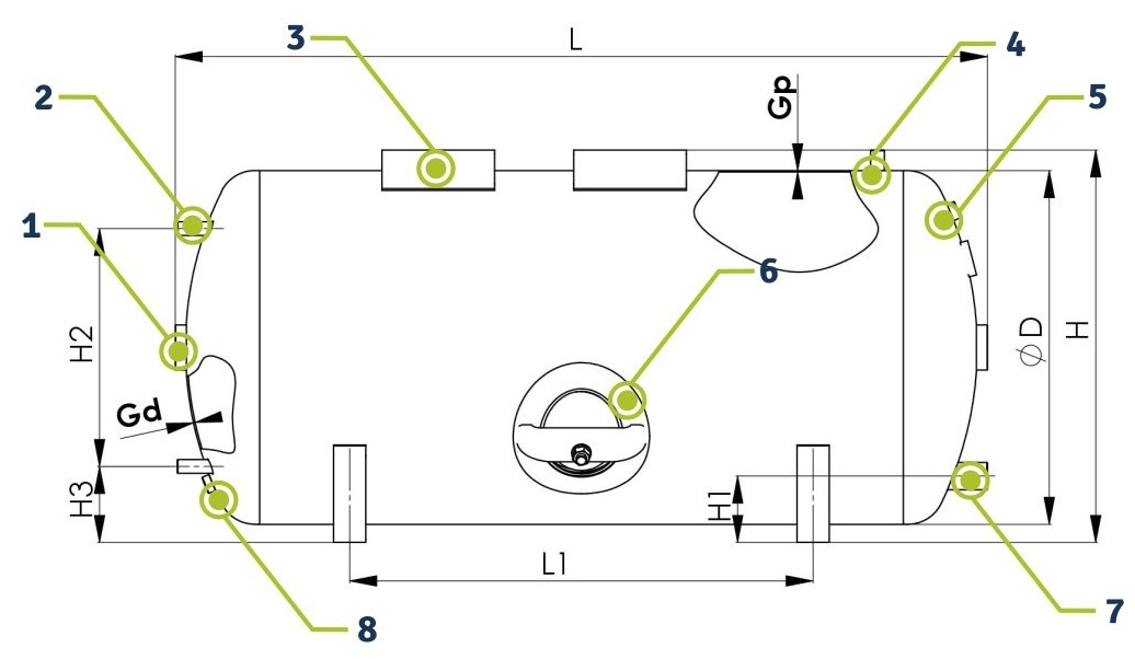
Description
|
1. |
Connector - G 2" |
|||||||||||||
|
2. |
Sight Glass Connector - G ½" |
|||||||||||||
|
3. |
Pump Base Plate (Tank HVP L 151 l includes a single base as standard) |
|||||||||||||
|
4. |
Connector Stub for LCA Pressure Switch - G ½" |
|||||||||||||
|
5. |
Stub for Plug with Valve G ½" |
|||||||||||||
|
6. |
Clean‑out |
|||||||||||||
|
7. |
Water Intake - G 1¼" |
|||||||||||||
|
8. |
Drain Outlet G ½" |
|||||||||||||
HVP L - Horizontal Tank Tevchnical Data
| Tank Type | Volume | Ø D | H | H1 | H2 | H3 | L | L1 | Max Pressure | Test Pressure | Temp. min./max. | Gp | Gd | Weight |
| [ l. ] | [ mm ] | [ bar ] | [ oC ] | [ mm ] | [ kg ] | |||||||||
| HVP L 151 | 150 | 500 | 557 | 98 | 345 | 106 | 880 | 450 | 6 | 8,6 | +6 / +20 | 2,0 | 2,5 | 34 |
| HVP L 201 | 200 | 550 | 610 | 103 | 370 | 118 | 972 | 500 | 42 | |||||
| HVP L 301 | 300 | 1262 | 720 | 50 | ||||||||||
Galvanized hydrofor tank
- Made of steel coated with a layer of zinc (protection against corrosion)
- No membrane – water is in direct contact with air
- Air and water mix inside
- In practice, this means that the air gradually dissolves in the water and needs to be replenished
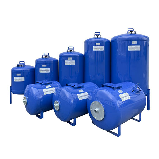
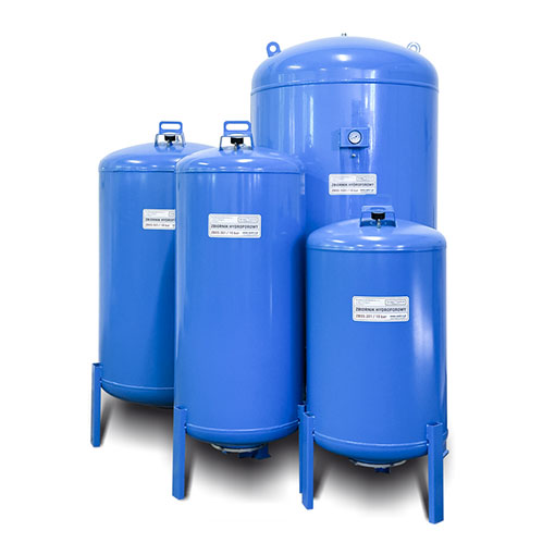
Diaphragm (membrane) hydrofor tank
- Contains a rubber membrane (bladder) inside
- Water is separated from the air
- Air is located between the tank wall and the membrane. Thanks to this, the pressure is more stable and the air does not escape into the water